The 120% Rule for Solar: Ensuring Electrical Safety in PV Installations
As solar energy adoption accelerates globally, understanding critical electrical safety standards like the 120% Rule becomes essential for homeowners, installers, and developers. This fundamental principle, embedded in the National Electrical Code (NEC) and reflected in international standards, safeguards electrical systems against potentially dangerous overheating. At Grace Solar, we prioritize safety in every solar mounting solution we design, ensuring compliance with these vital regulations.
The Physics Behind the Problem: Why the 120% Rule Matters
Traditional electrical panels are designed for unidirectional current flow - from the utility grid through the main breaker, across the busbars, and out to branch circuits. Solar installations disrupt this flow pattern by introducing reverse current from photovoltaic systems. This bidirectional energy flow creates a potential overheating hazard at the panel's busbars, the conductive metal strips that distribute electricity throughout the panel.
Busbars have specific thermal limits based on their material composition and cross-sectional area. When current exceeds these limits, temperatures can rise to dangerous levels, potentially melting insulation, damaging components, or in extreme cases, causing electrical fires. The 120% Rule establishes a safety buffer that prevents combined currents from surpassing the busbars' safe operating capacity.
Global Variations of the 120% Rule Principle
While the NEC's 120% Rule is the most referenced standard, similar safety principles exist worldwide with regional variations:
- International Electrotechnical Commission (IEC): IEC 60364-7-712 provides guidelines for solar PV supply systems
- Australia/New Zealand: AS/NZS 5033 mandates specific overcurrent protection requirements
- European Union: EN 62446 outlines system safety and performance requirements
- Canada: Canadian Electrical Code Section 64 includes similar derating requirements
Advanced Calculation Methodology
Proper application of the 120% Rule requires detailed electrical analysis:
Step 1: Determine Busbar Rating
Locate the manufacturer's label on the service panel. The rating is typically printed near the UL listing mark. Common ratings include 100A, 125A, 150A, 200A, and 225A.
Step 2: Calculate 120% of Busbar Rating
Example: 200A panel × 1.2 = 240A maximum combined current
Step 3: Identify Main Breaker Rating
Typically marked on the main breaker switch handle
Step 4: Calculate Maximum Solar Breaker Size
(Busbar Rating × 1.2) - Main Breaker Size = Max Solar Breaker
Real-World Implementation Challenges
Modern solar installations often encounter these practical challenges with the 120% Rule:
- Older Electrical Panels: Many homes built before 1990 have 100A or 125A service
- High Energy Consumption: Homes with electric vehicles or heat pumps require larger systems
- Commercial Applications: Businesses often need systems exceeding residential limits
- Retrofit Limitations: Physical constraints in existing buildings
Grace Solar's Engineering Solutions
Our solar mounting systems incorporate design features that facilitate compliance with electrical safety standards:
Integrated Conduit Management
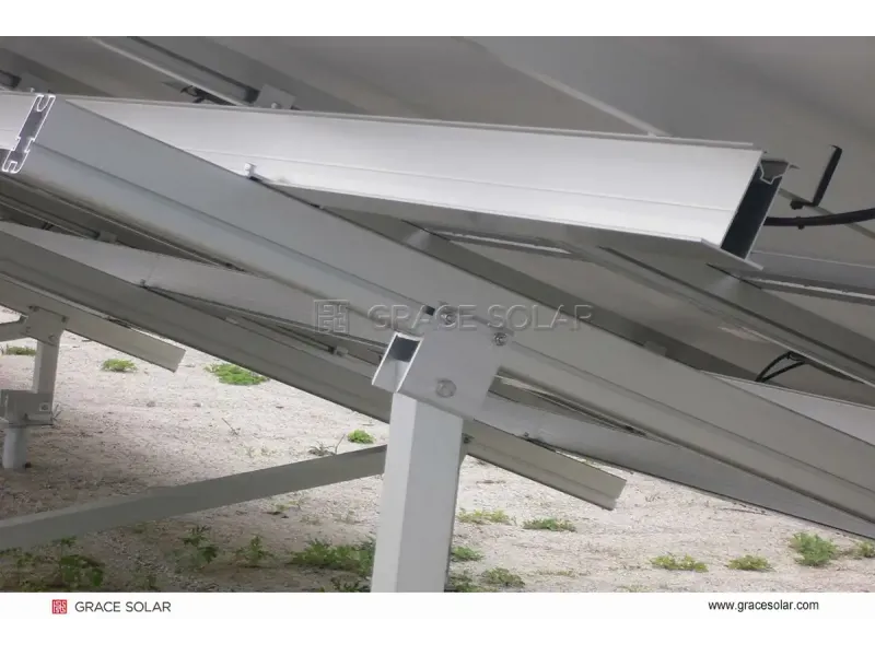
Our ground mount systems feature dedicated cable trays that maintain proper separation between DC and AC wiring, reducing electromagnetic interference and heat buildup.
Thermal Expansion Compensation
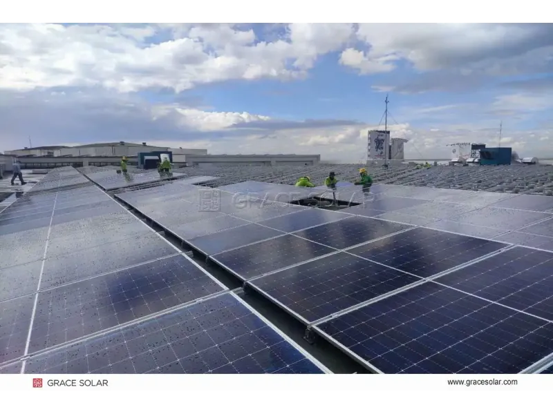
All roof mounting solutions include expansion joints that accommodate temperature-induced movement, preventing stress on electrical connections.
Advanced Airflow Design
Our single-axis trackers elevate panels to optimize passive cooling, reducing operating temperatures by up to 15°C compared to fixed-tilt systems.
Corrosion-Resistant Hardware
All components feature zinc-aluminum-magnesium coating, maintaining electrical continuity and preventing hot spots caused by corrosion.
Compliance Strategies for Large-Scale Installations
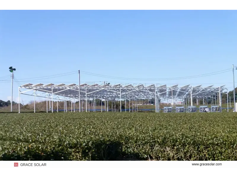
For utility-scale projects using our solar farm mounting systems, we implement advanced compliance approaches:
- Distributed Combiner Boxes: Reduce conductor lengths and voltage drop
- Medium Voltage Integration: Transformers located at optimal points in the array
- Dynamic Load Monitoring: IoT-enabled sensors throughout the system
- Selective Circuit Sizing: Custom conductor sizing per string configuration
Future-Proofing Solar Installations
At Grace Solar, we design our mounting systems with future electrical needs in mind:
- Battery Ready Designs: Dedicated spaces and pre-installed conduits for energy storage integration
- EV Charger Compatibility: Structural support for future charging infrastructure
- Module Agnostic Systems: Compatibility with next-generation high-wattage panels
- Smart Monitoring Integration: Junction boxes with IoT sensor ports
Global Certification Standards
All Grace Solar products meet international safety certifications relevant to electrical compliance:
UL 2703
Mounting Systems
IEC 62548
PV Array Design
AS/NZS 1170
Structural Design
JIS C 8955
Japanese Standard
Conclusion: Safety Through Engineering Excellence
The 120% Rule represents more than a regulatory requirement—it embodies the fundamental principle of designing electrical systems with appropriate safety margins. At Grace Solar, we extend this philosophy to every aspect of our solar mounting solutions, from structural calculations to corrosion protection.
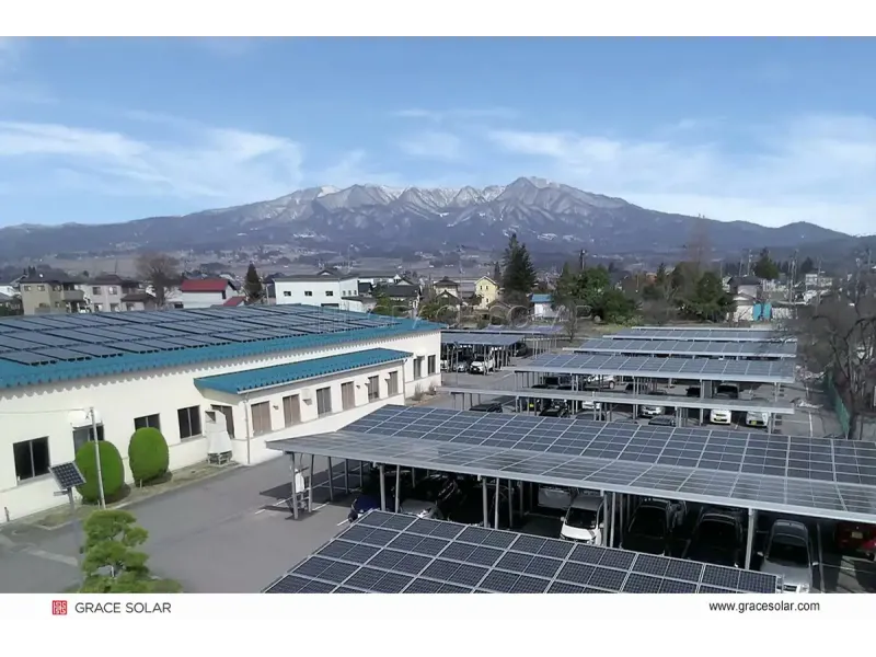
Whether you're installing a residential roof system, commercial carport, or utility-scale solar farm, our engineering team provides technical support to ensure your project meets all applicable electrical codes while maximizing energy production.
By combining code-compliant electrical design with precision-engineered mounting solutions, we help create solar installations that deliver safe, reliable, and optimal performance throughout their 30+ year lifespan—truly embodying our core value of "Do it right the first time".

